
LINE‑SIDE & BAY COVERAGE
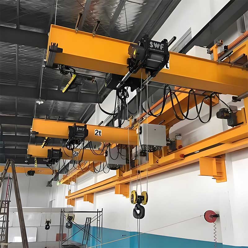
Wall‑Travelling Jib Crane (WTJ)
0.25–5 t · 2–10 m outreach · Up to 100 m travel · Low‑headroom cantilever · Manual/Electric trolley & travel
- Zero floor footprint
- Long bay coverage
- Busbar or festoon
- Pendant or radio
For areas bridge cranes can’t reach · CE/ISO compliant · Quick installation

- ISO 4301/4306
- FEM/ISO M3–M5
- CE Marking
- 1‑Year Warranty
- Spare Parts Support
Zero Floor Footprint
Travels on a wall/column runway; keeps aisles clear and cells compact.
Wide Coverage
2–10 m outreach with up to 100 m bay travel for continuous line‑side reach.
Precise Handling
Dual‑speed/VFD hoists; powered trolley/travel for effortless positioning.
Built‑In Safety
End‑stops, limit switches, e‑stop; optional anti‑spark kit (Ex) and bumpers.
Why Wall‑Travelling Jib?
- Serve the edges: perfect for bays where an overhead crane has blind spots.
- Fast retrofit: runway brackets to steel columns or RC walls with anchors.
- Operator‑friendly: pendant or radio control, smooth travel and start/stop.
- Low ownership cost: standard chain hoists and simple busbar/festoon electrics.
Build Your Spec
Budget Estimate
Auto‑updates from “Build Your Spec”. Budgetary range (ex‑works). Final quote after drawings & runway/structure check. *Ex versions priced with compliance documents.
- Capacity
- —
- Outreach
- —
- Under‑Boom
- —
- Travel
- —
- Travel Drive
- —
- Trolley
- —
- Duty
- —
- Control
- —
- Hoist
- —
- Power
- —
- Surface
- —
- Environment
- —
- Quantity
- —
- Timeline
- —
Applications & Examples
Technical Specifications
| Type | Wall‑travelling cantilever jib crane with runway along wall/columns |
|---|---|
| Rated Capacity | 0.25–5 t standard |
| Outreach | 2–10 m |
| Under‑Boom Height | 2–8 m |
| Travel Length | 5–100 m |
| Drives | Manual/electric trolley; manual or VFD travel; VFD hoist |
| Duty Group | ISO/FEM M3–M5 |
| Power | Busbar or festoon; energy chain optional |
| Mounting | Runway brackets to steel columns or RC walls (anchors/backing plates) |
| Safety | End‑stops, travel limit switches, e‑stop; optional bumpers & anti‑spark kit |
| Finish | Indoor epoxy; outdoor C3–C4 system; clean‑area coatings optional |
| Options | Radio remote, LED lighting, stainless hardware, cable reels/energy chain |
From Inquiry to Installation
- 01 · SizingShare load, outreach, under‑boom, travel length & column/wall details
- 02 · ProposalGA drawing & runway/bracket layout, budget
- 03 · ManufacturingFAT with load test
- 04 · DeliveryCrating & logistics
- 05 · InstallationOn‑site guidance or full install
Get Pricing & Lead Time
Tell us capacity, outreach, under‑boom height, travel length, travel drive, trolley, duty, control, hoist, power, mount surface & environment. We’ll tailor the runway, brackets, beam section and electrics to your site.
Note
*Runway/column capacity to be verified by client or our partner structural engineer.