
CYCRANE / Crane end trucks & travel interfaces
Crane End Carriages.
Coordinate the travel system.
Define the crane.
Match the wheels, rails and drive.
Plan top-running or underslung end-carriage requirements for single- and double-girder cranes. Bring the actual crane loads, runway profile, mounting and drive details into one technical enquiry.
- Top / UnderslungMounting directions
- Single / DoubleGirder requirements
- Wheels & drivesInterface review
- New build & replacement
- Wheel / rail coordination
- Mounting & drive review
 END CARRIAGES / LOADS, RAILS & INTERFACES
One coordinated crane travel package.Bring the runway profile and actual wheel reactions.
- 01Define the crane
- 02Review the runway
- 03Coordinate the drive
01 / Mounting directions
Start with the runway.
Define the end-truck package.
Mounting and crane structure guide the mechanical interfaces. Actual wheel reactions, running surfaces and drive arrangement determine the final model.
Top-Running End Carriages
Share the crane wheel reactions, rail profile, span/gauge and girder connection. Coordinate wheel tread/flange geometry and runway alignment.
Underslung End Carriages
Provide the complete running-beam flange/profile, wheel arrangement, connection dimensions and clearances for the proposed suspended travel package.
02 / Selection guide
Loads on the wheels.
Details at every interface.
Use the actual crane and runway data where available. Average wheel load and simple dimension bands cannot establish the final wheel or rail compatibility.
Actual wheel reactions
Include bridge/trolley dead weights, trolley positions, wheelbase, lifting loads and operating load cases.
Rail & flange profile
Share rail designation, tread width/profile, flange thickness, running surface and clearances, especially for underslung travel.
Motion & architecture
Define speed, acceleration, active drive count, gearing, motor/control supply and the braking requirements.
Connection & alignment
Provide girder connection drawings, gauge, wheel arrangement, duty, environment and requested accessories.
03 / Configure & plan
Build the end-carriage enquiry.
Review the assumptions.
Record the crane, travel and interface requirements. The original quantity budget is preserved. Load, diameter, length and power references are simplified discussion values, not selected catalogue ratings.
Your End-Carriage Configuration
Use sliders or direct number entry. Quantity is in pairs; the wheel count is for one pair. Add actual wheel reactions, crane weights, rail profile and drive details in the notes.
01 / Crane arrangement
02 / Wheels, drive & runway
03 / Environment
04 / Accessory requests
04 / Technical scope
Wheel, runway and drive.
A coordinated end-truck package.
These source scope areas and reference ranges require confirmation for the actual model and crane. Materials, duty, finish and accessory requirements follow the project proposal.
| Configuration | Top-running or underslung; single- or double-girder |
|---|---|
| Capacity | Original planning range: 1–200 t cranes; higher requests subject to engineering and supply confirmation. |
| Wheel Ø | Original planning band: 160–500 mm; actual diameter and wheel rating require wheel-load, rail and duty review. |
| Wheels | Forged steel, SG iron or other material requests subject to actual model and application review. A bronze/spark-resistant material request does not establish hazardous-area approval. |
| Bearings | Bearing type, seals and lubrication confirmed for actual loads, model, duty and environment. |
| Drive | Geared motor, inverter compatibility and brake/holding requirements confirmed for the actual drive architecture. |
| Speed | 10–80 m/min |
| Duty | M5–M7 requirement inputs; applicable classification and design evidence confirmed separately. |
| Protection | IP55 standard, IP65 optional |
| Options | Rail sweepers, buffers, anti-derail, travel limits, anti-collision |
| Finish | Epoxy/polyurethane and corrosion-class requests, including original C3–C5M wording, require the actual exposure, coating system and applicable specification to be agreed. |
| Documentation | GA drawings, wheel load calculation, motor data, manuals |
No wheel, rail, bearing or motor is selected by the planning calculator. Confirm individual maximum reactions, wheel/rail contact, structural geometry, drive duty and project documentation.
05 / Product references
See the arrangement.
Define the connection.
Original website images show end-carriage products and overhead-crane arrangements. They do not prove exact ratings, wheel-block details or a confirmed customer case.
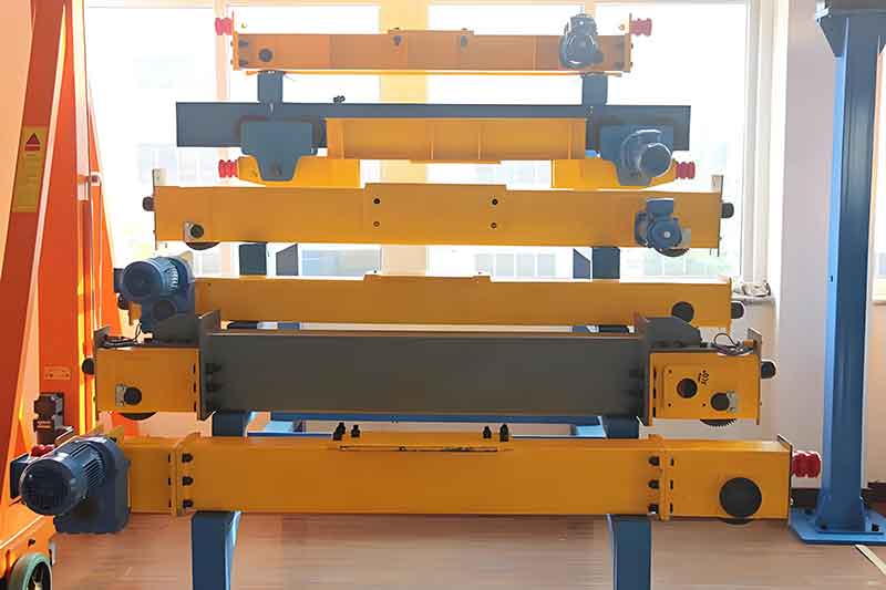
End-carriage product display
Website reference. Confirm the actual mounting, components and supplied scope.
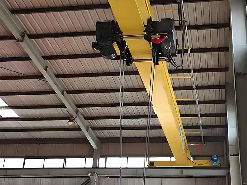
Overhead-crane and travel arrangement
Website reference. Confirm the actual mounting, components and supplied scope.
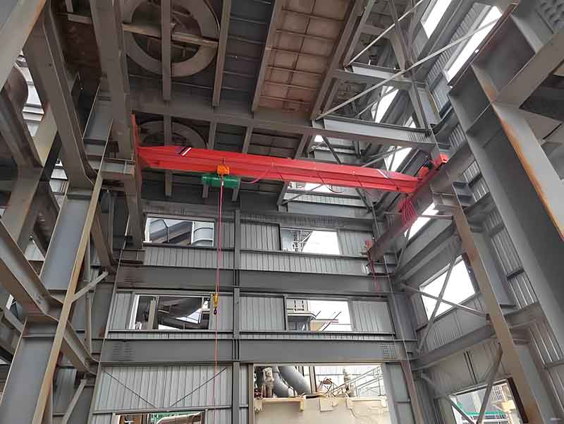
Crane installation layout reference
Website reference. Confirm the actual mounting, components and supplied scope.
06 / Project steps
From crane data
to an agreed travel package.
Review the layout and model, then agree the manufacturing, inspection and installation-support scope.
Sizing
Crane loads, runway, duty and speed.
Proposal
Review wheels, drives, interfaces and budget.
Manufacture
Confirm fabrication, assembly and inspection.
FAT
Agree alignment and function test scope.
Commissioning
Confirm documents and site support.
07 / Before you specify
Planning replacement
or a new crane travel system?
Actual crane reactions and runway geometry guide the package.
Discuss My End-Carriage Requirements ↗What information is needed for a replacement?
Send existing nameplates and photos, crane weights and maximum wheel reactions, rail/beam profile, wheelbase, wheel and girder-connection dimensions, drive arrangement, speed, duty and environment.
Does the average wheel load determine a safe wheel size?
No. The original model estimates bridge/trolley mass and divides an averaged factored load across the wheels. Actual maximum wheel reactions depend on trolley position, real dead weights and load cases. The diameter band does not select a rated wheel.
Why are there two power figures?
The original power formula used tonnes where kilograms were needed and included a 0.18 kW floor. It is retained only for comparison. The separate reference corrects the mass units, using the same steady-travel assumptions and assumed active-drive count. Neither selects a motor.
Does the rail-width check approve the runway?
No. It is only an illustrative width threshold based on the original diameter band. Actual tread/flange geometry, contact, loads, tolerances and structural compatibility need the rail or beam drawing, especially for underslung travel.
Do span and mounting change the original budget?
The original model records span, mounting and rail width without separate price factors. High Temp also has no independent factor. These inputs still matter to the actual engineered configuration and quotation.
Is the budget per carriage or for the entered quantity?
It is the original EXW equipment total for the entered number of pairs. One pair means two carriages; the displayed wheel count is per pair. Timeline choices are requests. Actual supply scope, price and delivery need a quotation.
08 / Technical & commercial enquiry
Send the end-carriage requirements.
Bring the crane and runway data.
Your configuration, planning outputs, assumptions and pair-quantity budget are included with the enquiry. Add the existing equipment, actual reactions and supporting drawings.
- WhatsApp / phone+86 155 1554 5327
- Sales enquiriessales@cy-cranes.com
- Talk about your projectCall +86 155 1554 5327
Useful details: crane/end-truck nameplates, wheel reactions, runway profile, wheelbase, mounting drawings, active drives, speed, acceleration, duty, actual temperature, pair quantity and destination.
End-Carriage Technical RFQ
Start with your email and destination. Add the project details you already know.
Review the configuration included with your enquiry
Error: Contact form not found.
Prefer email? Send your configuration ↗