
CYCRANE / Moving power for bridge, gantry & monorail
Crane Power Systems.
Follow the moving route.
Define the route.
Coordinate power, cables and clearance.
Explore conductor bar, festoon, cable reel and energy-chain requirements. Bring travel length, speed, electrical demand and installation conditions into one coordinated power-system enquiry.
- 4 system typesPlanning directions
- Bridge / CT / YardRoute review
- Power & controlComponent coordination
- New build & retrofit
- Route & feed layout
- Clearance & environment review
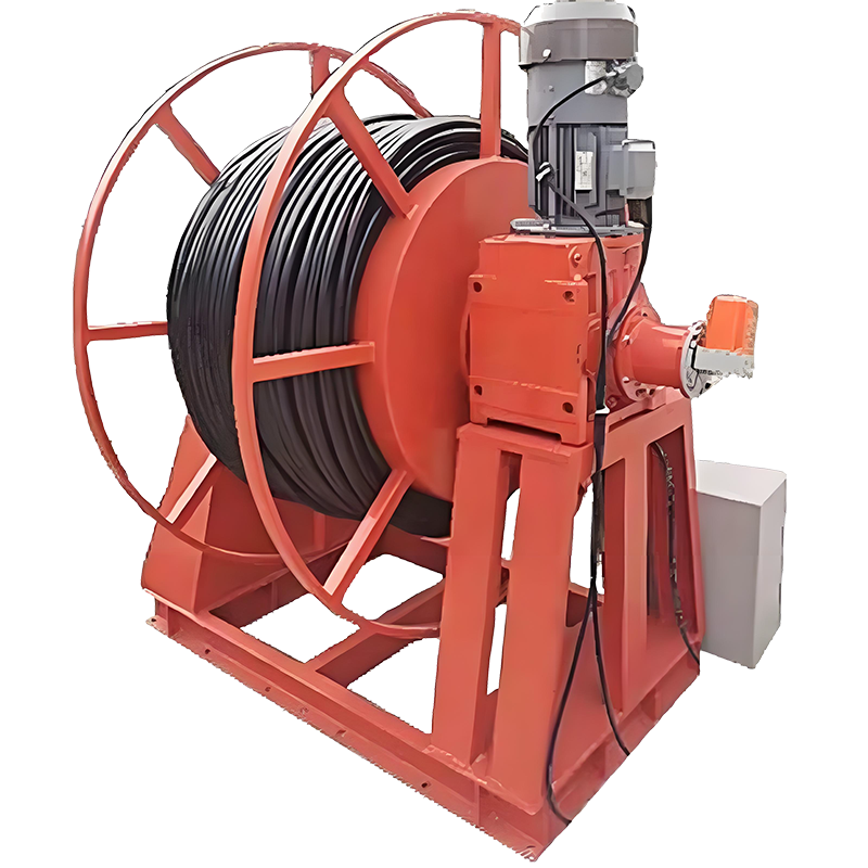 MOVING POWER / ROUTE, LOAD & CLEARANCE
Power along the travel path.Bring the feed points, cable package and working space.
- 01Define the route
- 02Record the loads
- 03Review the layout
01 / System directions
One moving route.
Four system directions.
The system follows the electrical load, mechanical route, space and working conditions. Use the builder for an initial budget scenario, then confirm the layout and component package.
Conductor Bar
Coordinate conductor layout, current demand, collector paths, feeds, joints and environmental protection.
Festoon Systems
Review cable weight, trolley loading, travel and parking length, loop clearance and bending requirements.
Cable Reels
Define travel route, cable length and weight, reel position, winding arrangement and cable tension.
Energy Chains
Coordinate cable/hoses, dynamic bend radius, fill, support/trough geometry, speed and acceleration.
02 / Layout guide
Electrical demand above.
Mechanical clearance alongside.
Coordinate the route and feeds before defining the component package. Length and speed thresholds in the planning model are not product ratings.
Travel & parking
Provide actual travel, curves, branches, feed locations, end positions and available storage/parking space.
Load & supply
Record simultaneous current, power/control circuits, supply, pole functions and required protective-earth continuity.
Cables & support
Include cable/hoses, dimensions, weight, bending requirements, supports, trolley loads and available clearance.
Exposure & access
Describe weather, corrosion, dust, temperatures, inspection access and any classified-area requirements.
03 / Configure & plan
Build the power-system enquiry.
Review the route assumptions.
Record travel, speed and electrical requirements. The original rules produce a budget scenario; they do not select a rated system or establish environmental/hazardous-area approval.
Your Moving Power Requirements
Use the slider or number box for length and speed. Add a preferred system, actual layout and cable/load details in the notes. The budget covers the configured route/package, with no multi-system quantity input.
01 / Route & operating duty
02 / Electrical demand
03 / Project requirements
04 / Technical scope
Route, feeds and components.
One coordinated specification.
Review the source scope areas against the actual system proposed. Current ranges, installation geometry and environmental execution need model and layout confirmation.
| Conductor Bar | Enclosed 4/5-pole and 60–500 A planning range; feeders/end caps, expansion joints, collectors and outdoor provisions confirmed per actual model/layout. |
|---|---|
| Festoon | C-track/I-beam, flat-cable trolleys, tow trolley/end clamp and junction box requests. Original 1.0–1.5 m spacing reference is subject to cable load, geometry and actual trolley model. |
| Cable Reel | Spring or motorized; slip ring; level-winding; torque/speed control; suitable for long LT runs or port yards. |
| Energy Chain | Polymer/steel chain, bend radius by cable/hoses; guide trough; for high speed CT or tight clearance monorails. |
| Voltage | 380–480 V, 50/60 Hz, 3Ph; control 24–110 V AC/DC; 4/5-pole layouts; earth continuity provisions. |
| Environment | Indoor/outdoor, marine, UV/ozone and temperature requirements; hazardous-area requests require classification, exact equipment evidence and project review. No ATEX/IECEx approval is established by the builder. |
| Docs | Layout drawing, BOM, installation guide; FAT report/photos on request. |
The builder records requirements and estimates a route budget. Actual electrical ratings, supports, bend radius, environmental suitability and final BOM require engineering review.
05 / System references
See the moving interface.
Define the working space.
Original website photographs show the system arrangements. They do not establish a confirmed customer case, rating or environmental approval.
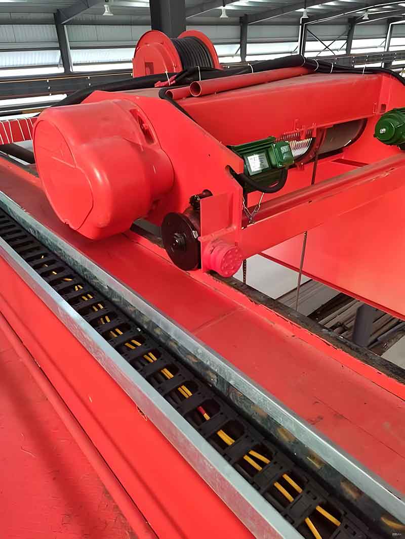
Hoist trolley and energy-chain arrangement
Website reference. Confirm exact components, route and supply scope.

Hanging festoon cable-loop arrangement
Website reference. Confirm exact components, route and supply scope.

Conductor-bar and collector interface
Website reference. Confirm exact components, route and supply scope.
06 / Project steps
From route data
to an agreed power package.
Define the installation, review the layout and agree the manufacturing, inspection and support scope.
Sizing
Moving length, duty, speed and current demand.
Proposal
Review system layout, BOM and budget.
Manufacturing
Confirm component, inspection and packing scope.
Installation
Agree mounting, connection and site work scope.
Commissioning
Confirm documentation and support requirements.
07 / Before you specify
Planning a new route
or a power-system retrofit?
Actual electrical loads and installation geometry guide the system.
Discuss My Power Requirements ↗Does the automatic scenario select the right system?
No. It preserves the original length, speed, application and environment rules for early budget discussion. Those thresholds are not catalogue limits. Actual electrical and mechanical requirements determine the final choice.
What does the ATEX/IECEx option do?
It records a hazardous-area request. The original price model switches to a conductor-bar scenario with a 1.35 factor. That is retained only as a legacy budget assumption; it does not identify suitable certified equipment or prove approval. Provide actual area classification and project requirements.
Are the voltage and pole choices included in a complete design?
They are recorded in the enquiry. The original price model has no independent voltage or pole-count factor, and does not calculate voltage drop, heat rise, protective-earth arrangement or fault-current capability. Confirm them in the final layout and BOM.
Can I request a different system from the scenario?
Yes. State your preferred conductor bar, festoon, reel or energy-chain arrangement in the project notes and send a layout. The displayed range remains the rule-based scenario budget; the alternative needs its own technical proposal.
Does the cable length or trolley count represent the final BOM?
No. They are simplified component assumptions. Confirm actual cable routing, feed location, parking, cable weight, dynamic bend radius, supports, reel/chain geometry and installation scope.
Is the displayed price a multi-system total or a confirmed lead time?
It is an indicative EXW budget for the configured route/package. The source has no system-quantity input. Timing choices are requested targets. Final system count, scope, price and delivery require a written quotation.
08 / Technical & commercial enquiry
Send the power requirements.
Bring the route and load data.
Your selected requirements, budget scenario and model assumptions are attached to the enquiry. Add your preferred system, existing components and supporting files.
- WhatsApp / phone+86 155 1554 5327
- Sales enquiriessales@cy-cranes.com
- Talk about your projectCall +86 155 1554 5327
Useful details: route/feed drawings, moving and parking space, simultaneous loads, pole functions, cable package, clearance, environment, preferred system, actual quantities and destination.
Crane Power-System Technical RFQ
Start with your email and destination. Add the project details you already know.
Review the configuration included with your enquiry
Prefer email? Send your configuration ↗