
CYCRANE / Lifting beams, spreader bars & frames
Lifting Beams.
Define the complete arrangement.
Start with the load.
Coordinate lift points, headroom and rigging.
Plan lifting-beam and spreader requirements around the actual load and lifting geometry. Bring requested capacity, span, centre of gravity, connections and document requirements into one technical enquiry.
- Beam / SpreaderSystem directions
- Fixed / AdjustableConfiguration requests
- Load & riggingArrangement review
- Load & lift-point data
- Connections & headroom
- Project-specific proposal
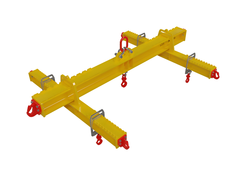 BEAMS & SPREADERS / LOAD, GEOMETRY & CONNECTIONS
The lifting arrangement guides the package.Bring actual weight, lift points and COG coordinates.
- 01Describe the load
- 02Define the geometry
- 03Review the package
01 / System directions
Define the load path.
Compare the beam arrangement.
Select a starting type for the enquiry. The actual configuration, connections, ratings and test scope follow the load and rigging drawing.
Two-Point Spreader Bar
Review the top and bottom sling geometry, available headroom, load points and actual arrangement.
Two-Point Lifting Beam
Define the top connection and lower lift points, actual load/COG and the available installation envelope.
Telescopic Spreader
Specify working spans and adjustment positions. Ratings and locking arrangements follow the exact proposed configuration.
Modular Spreader
Record span combinations, connections and intended load cases. Confirm ratings for each assembled arrangement.
Four-Point Lifting Beam
Provide all lift-point and COG coordinates, geometry and load-sharing details for a configuration-specific review.
02 / Arrangement guide
The load has a centre of gravity.
The rigging has a geometry.
Requested capacity and span start the discussion. Actual lift-point coordinates, beam/rigging weights and top/bottom connections determine the final arrangement.
Mass & COG
Provide actual load mass, dimensions, centre-of-gravity coordinates and any handling restrictions.
Coordinates & reactions
Show all attachment points, their spacing and connection details. Off-centre and four-point lifts need a specific load-sharing review.
Angle & headroom
Define top/bottom sling lengths and angle conventions, hook interface, available height and below-hook equipment weight.
Service & documents
Record operating cycle, environment, finish, accessories and the required inspection/documentation scope.
03 / Configure & plan
Build the beam enquiry.
Review a planning budget.
Record the requested capacity and arrangement. The original price model is retained; it does not determine rated WLL, sling forces, compression, bending or structural suitability.
Your Lifting-Beam Requirements
Requested WLL is an input, not an approved rating. The angle is recorded from the horizontal here; confirm the convention on the drawing. Add full lift-point/COG coordinates and actual rigging geometry in the notes.
01 / Load & configuration
02 / Supply requirements
03 / Accessory & document requests
Shackles, pins, load cells and proof-load/NDT documents require the actual supply and test scope to be agreed.
04 / Technical scope
Load, beam and rigging.
A coordinated specification.
These source ranges and scope areas are discussion references. Confirm the exact configuration, rating, project specification and test/document requirements in the proposal.
| Types | Fixed lifting beam, spreader bar, telescopic spreader, modular bolted spreader, 4-point beam |
|---|---|
| WLL | Original planning range: 1–200 t requested WLL, higher requests subject to review. No rating is established by the calculator. |
| Spans | Original typical span reference: 1–12 m; telescopic/modular requests require configuration-specific ratings and connection review. |
| Connections | Top bail/master link; bottom shackles/hooks; multi-hole padeyes |
| Finish | Industrial paint or hot-dip galvanizing |
| Standards | Project may require EN 13155 and/or ASME BTH-1 design provisions. Confirm applicable scope, edition and evidence; the builder establishes no compliance. |
| Tests | Proof-load report and NDT (UT/MPI) as requested and agreed; selecting a document option is not a completed test or certificate. |
| Options | Load cells, low-headroom bails, quick-pins, sling sets |
Requested WLL, service class and span do not by themselves establish structural suitability. Confirm load cases, material, connections, buckling/bending, fatigue, rigging interfaces and agreed test scope.
05 / Product references
See the arrangement.
Define the interfaces.
Original website photographs show beam and lifting-attachment references. Images do not establish the rating, adjustability or suitability of the proposed configuration.
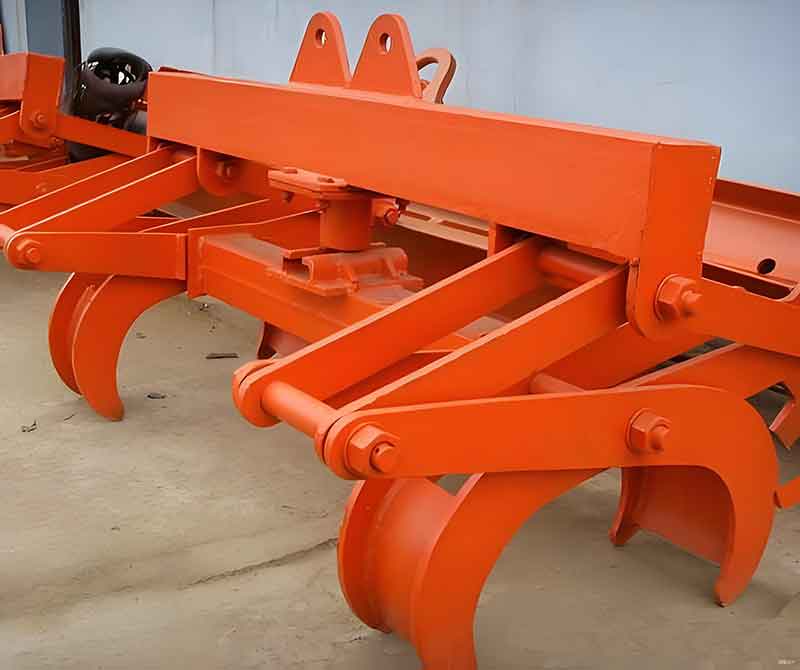
Beam with mechanical gripping attachment
Website reference. Confirm exact equipment, rated configuration and supply scope.

Beam with suspended lifting magnets
Website reference. Confirm exact equipment, rated configuration and supply scope.

Beam-and-chain lifting arrangement
Website reference. Confirm exact equipment, rated configuration and supply scope.
06 / Project steps
From load geometry
to an agreed lifting package.
Review the design inputs and configuration, then agree the manufacturing, test and documentation scope.
Inputs
Actual load, lift points, COG and headroom.
Proposal
Review configuration, connections and budget.
Manufacture
Agree material, fabrication and inspection scope.
Testing
Confirm proof-load/NDT requirements and records.
Delivery
Agree drawings, manuals and support scope.
07 / Before you specify
Planning a beam
or spreader-system enquiry?
Actual load and rigging geometry guide the configuration.
Discuss My Lifting Arrangement ↗Does entering WLL select an approved beam?
No. It records the requested rated capacity. The actual device rating depends on its specific model, span, configuration, connections and design verification. Provide actual load and rigging data for a rated proposal.
How do a lifting beam and a spreader differ?
They use different load paths: a lifting beam generally carries bending, while a spreader is arranged primarily for compression through its rigging. Actual top/bottom connections, loads and available headroom determine the appropriate configuration.
Does the builder calculate sling forces or bending?
No. The original generic snapshot had incomplete load/geometry assumptions and unit issues. The new page retains the budget and all request inputs, without presenting those force values as engineering results or a lifting approval.
What information is needed for an offset COG or four-point lift?
Provide actual load mass, all lift-point and COG coordinates, sling lengths/angles, connection positions and stiffness/load-sharing details where applicable. A single offset value or assumed equal load per point is not enough.
Do the proof-load and NDT options provide completed documents?
They record requested supply/test scope. Agree the applicable specification, test arrangement, acceptance requirements and documentation in the proposal. Selecting the option does not establish certification or a completed test.
Is the displayed range per unit or for the quantity?
It is the original EXW equipment total for the entered quantity, including its discount and urgency assumptions. Angle and COG have no independent original price factors. Final configuration, scope, price and delivery require a quotation.
08 / Technical & commercial enquiry
Send the lifting-beam requirements.
Bring the load and rigging drawing.
Your selected requirements, budget assumptions and quantity total are attached to the enquiry. Add actual load/COG data, full geometry and supporting files.
- WhatsApp / phone+86 155 1554 5327
- Sales enquiriessales@cy-cranes.com
- Talk about your projectCall +86 155 1554 5327
Useful details: load mass/geometry, lift-point and COG coordinates, sling lengths/angles, beam and rigging dead weight, hook/headroom, service, documents, quantity and destination.
Lifting-Beam Technical RFQ
Start with your email and destination. Add the project details you already know.
Review the configuration included with your enquiry
Error: Contact form not found.
Prefer email? Send your configuration ↗